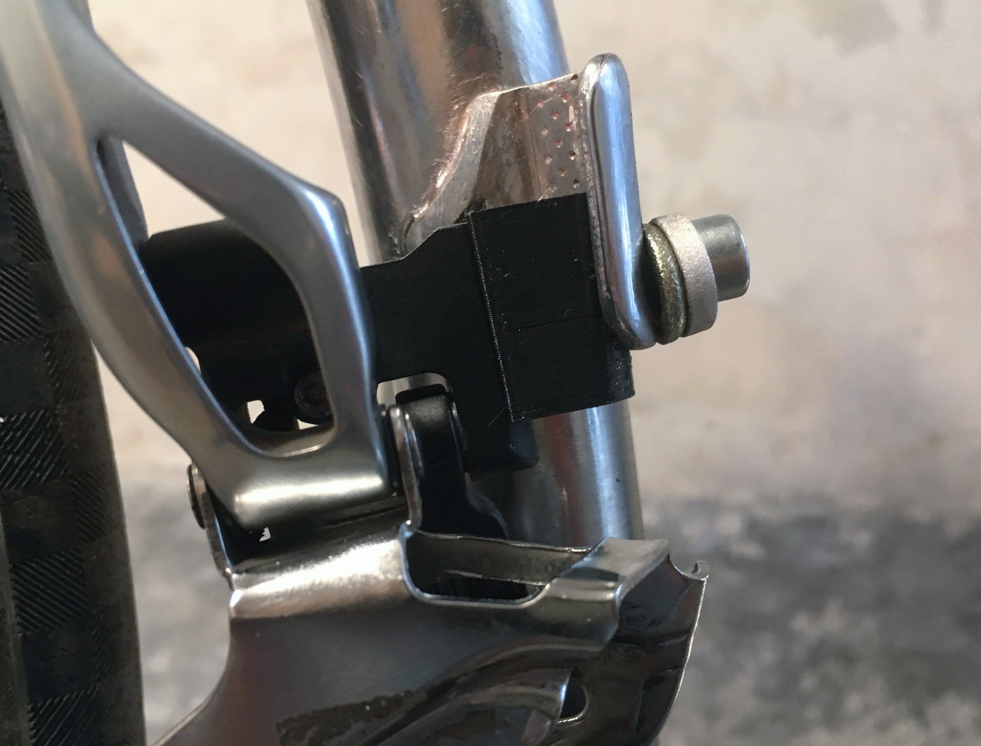
Front derailleur spacer
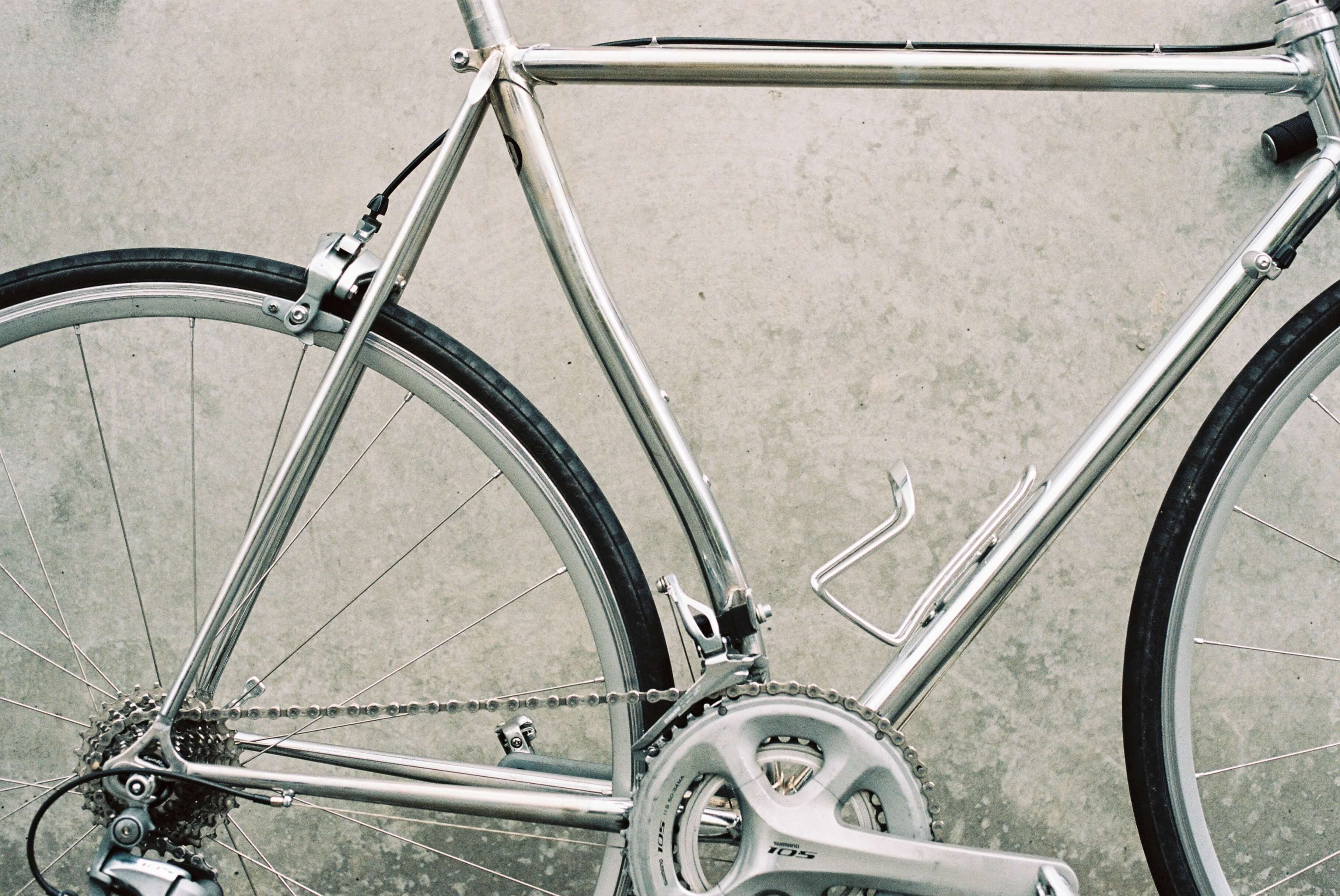
Recently, I got this steel frame to build kind of a neo-retro road bike) out of it. The frame has this perverse S-shaped seat tube. It looks cool but places the front derailleur too high and forward resulting in the chain rubbing against the bottom of the cage. I designed this little spacer that goes between the derailleur and the frame to move the derailleur back and down and to rotate it a few degrees - effectively rotating it around the cranks’ axis.
It works roughly like this:
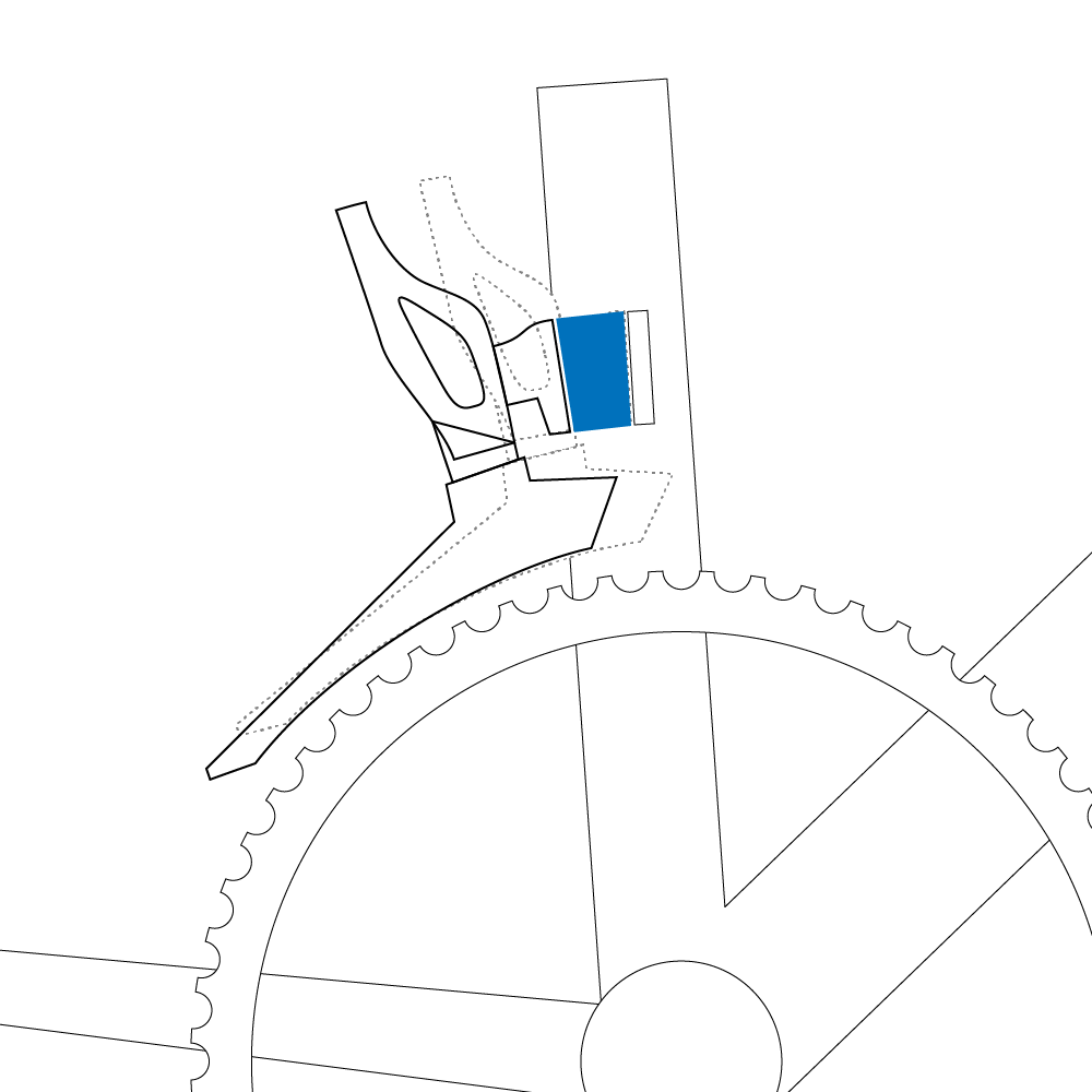
I couldn’t simply lower the derailleur as it would interfere with the big ring.
The modeling process was an unsettling experience. After the years of arguing about API designs, frameworks, code colour, architecture, paradigms (all these somewhat high abstractions) I was bodging together a scad file. Composed basically of one big formula with basic set operations (think
A ∪ B ∩ C \ A) and I wasn’t able to come up with a way of composing that formula as simply as possible. I felt like back in the time sitting at the Introduction to logic dulled by two beers, barely listening. I mean, this is as basic as it gets, yet my ‘experience’ with all these meta concepts is useless. I think I should get to ground a bit. Taste the fundamentals every so often. The corner stones like maths, algorithms, languages. Fresh myself up a bit!
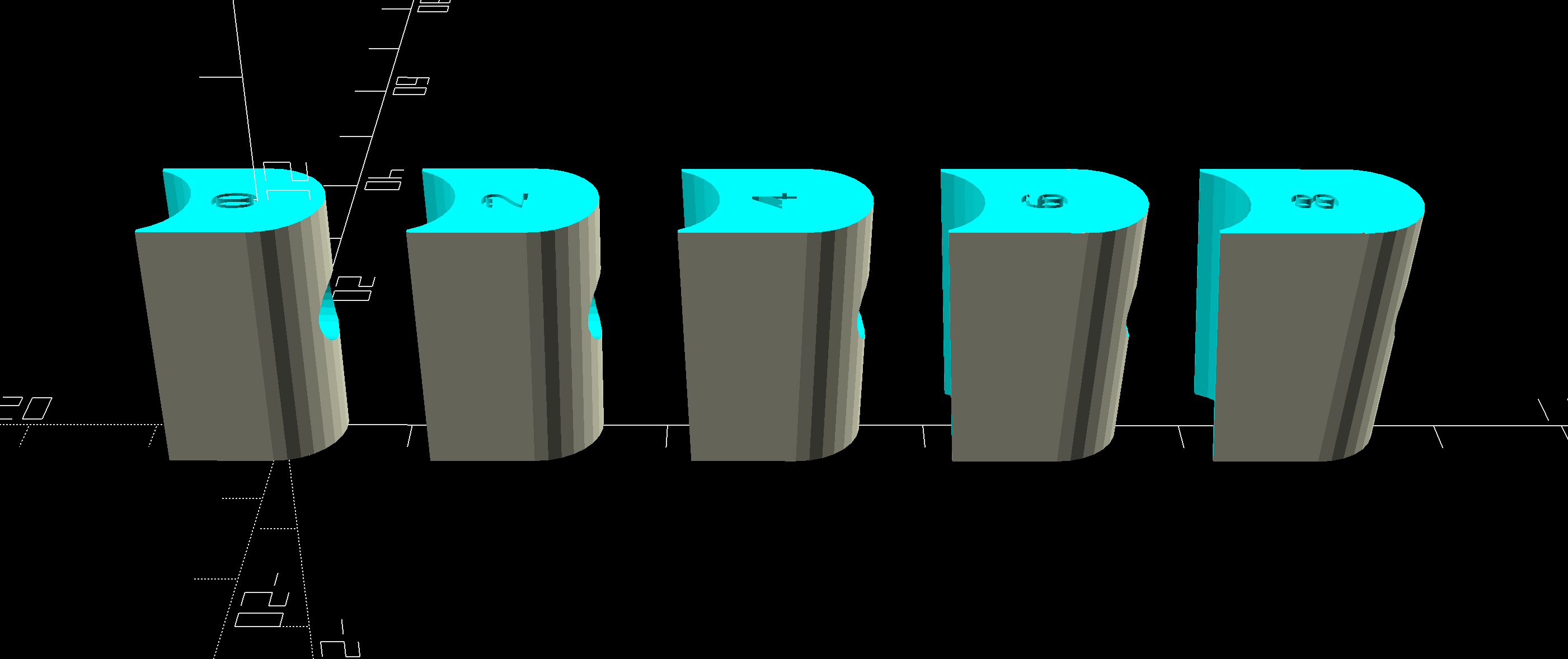
I tried to make the design parametrized so that it’s easy to adjust the most important features: 1) the angle by which the derailleur is tipped down 2) the offset in the backwards direction and 3) the bolt diameter. The parameters aren’t scalable infinitely though they should cover most practical use cases. The following image shows 5 variants with 2 degree increment.
The part should be printed with a goal of making it as much compression resistant as possible. I figured I’d use about 95% infill and 3-4 layers of shell. Honestly, I have no idea what I did here. Any advice on this is appreciated.
The hole diameter is set to be 0.5 mm larger than the given bolt diameter compensating for the printing inaccuracy. However, cleaning the hole with a drill might be required.
The spacer must be combined with a bolt with such a head that it can be angled relative to the surface it clamps against. One may use a regular bolt underlaid with the spacer pair found on most v-brake pads. That’s what I used and it worked well, though is a bit ugly. Certain designs of seat post saddle clamping mechanism (Thomson and friends) use bolts with bottom-rounded heads paired with a single rounded washer. These would probably give better looks.
The source scad files are available at GitHub and Thingiverse. Any feedback or pull requests warmly welcomed!
Sharing is caring.